Engineering Drawing Gd T Symbols Pdf
3 why should gd t be.
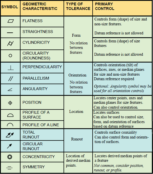
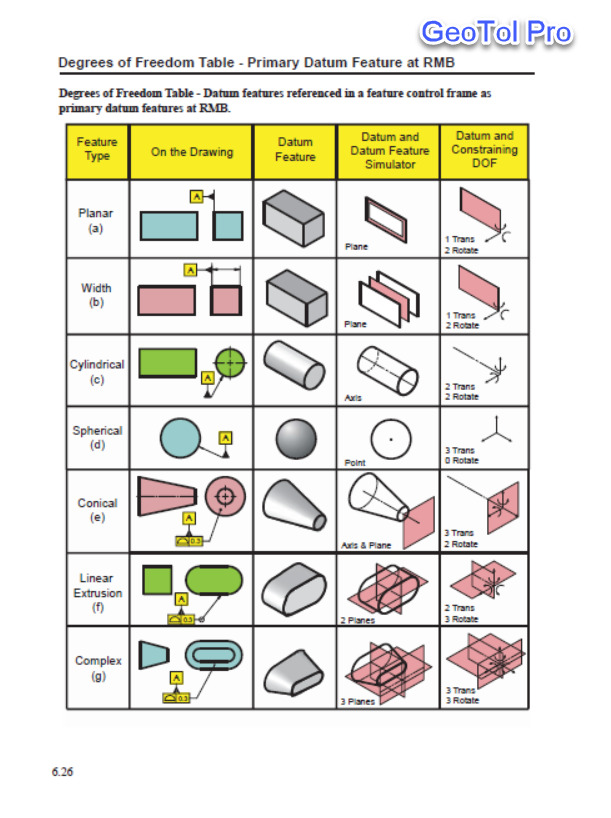
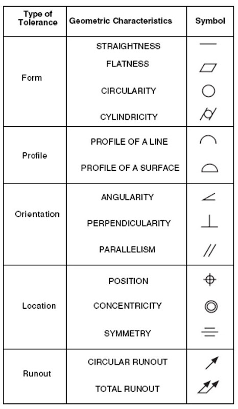
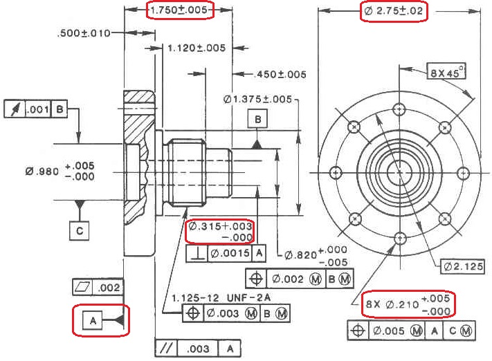
Engineering drawing gd t symbols pdf. It is compilation of symbols and rules that effi ciently describe and control dimensioning tolerancing for all drawings castings machined components etc. You can view all of the topics reviewed in this course by clicking here to view the course curriculum. Asme and iso standands related to product defination and metrology pdf. A gd t drawing uses standard symbols to describe a part.
Implied datum in plus minus tolerance is not clear implied datum is nothing but the assumed origin to fit the part in an imaginary coordinate system. Aligned dimensions have text placed parallel to the dimension line with vertical dimensions read from the. 2 what is gd t. Please draw circularity and perpendicularity symbol blocks with geometric tolerance of 0 005 for each and sketch their.
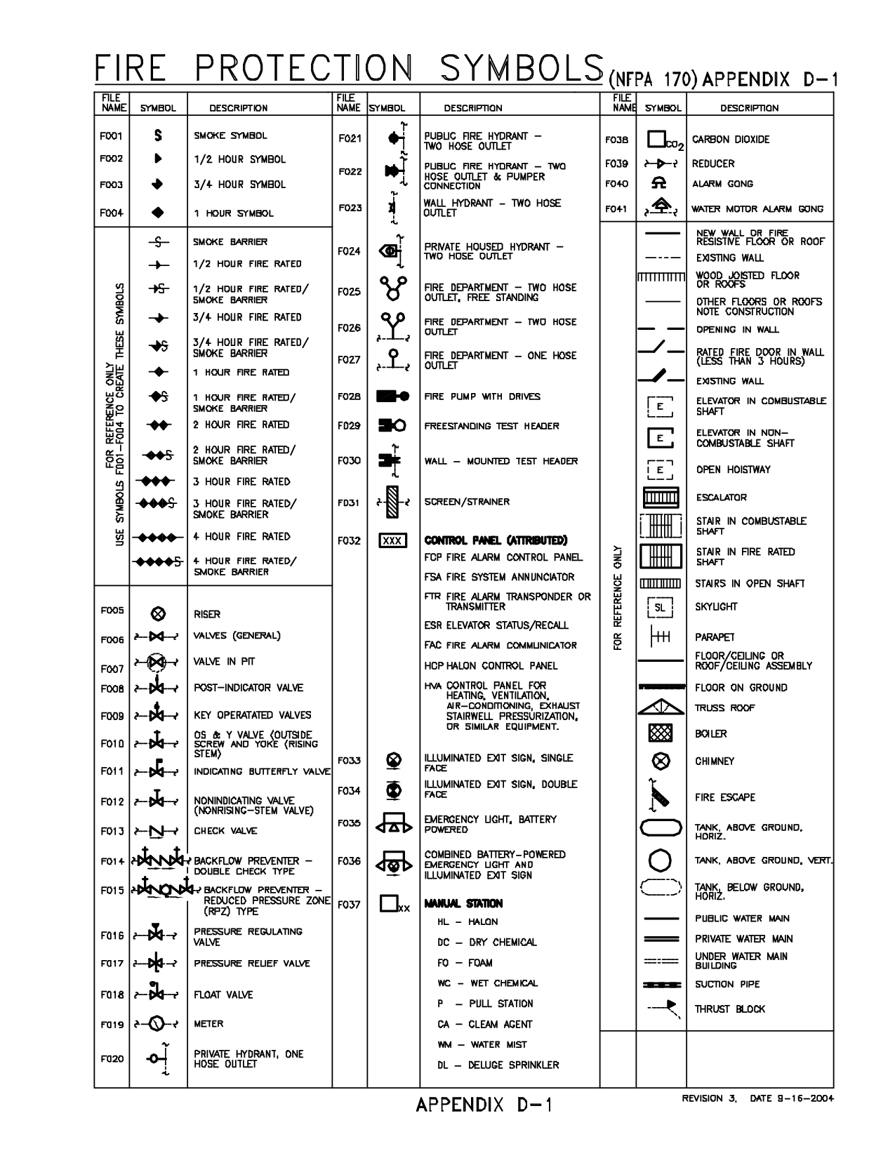
Structural steel profiles are not drawn in most cases nor are welds drawn or sketched as shown on the next page. Gd t tolerance type and symbols. Also asme y14 8 has guidance for casting and forging drawings. The best method for describing how the.
I had great response from scott s class. As with all new systems there is a learning curve with gd t. Print reading engineering drawings. Gd t tells the manufacturer the degree of accuracy and precision needed for each controlled feature of the part.
Comments i heard back was things such as. Placement of all text to be read from the bottom of the drawing is called unidirectional dimensioning. It is documented in asme y14 5m which has the symbols rules and simple examples. Gd t symbols chart.
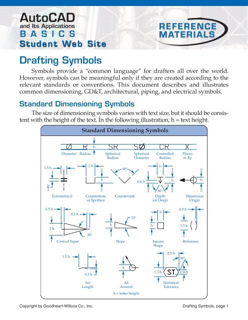
A part drawing may include a single gd t callout or the drawing may be fully defined using gd t depending on part requirements. Engineering drawing must be interpreted by everyone in exactly the same way to achieve a quality part that suits the design requirement. Identify the common symbols found on an engineering drawing and understand the meaning of each. Standard practices reading direction all dimension and note text must be oriented to be read from the bottom of the drawing relative to the drawing format.
Gd t is a way of specifying engineering design and drawing requirements with particular attention to actual function and relationship of the part features. Gd t allows for comprehensive and consistent tolerances with the use of relatively simple tools. Understand dimensioning methods used on an engineering drawing and what dimensional tolerances really mean. Structural steel profiles and welding symbols the purpose of this page is to introduce you to some other symbols and abbreviations that are quite common on engineering drawings.

